Guidelines for laser-cut parts
This page summarizes the design rules and production limits for laser-cut parts. It covers part dimensions, CAD file requirements, minimum features, thread-hole preparation, bridge tabs for cut letters, and corner-rounding recommendations.
Part Dimensions
- Maximum size for laser-cut metal parts: 2980 x 1480 mm
- Maximum size for laser-cut non-metal parts: 1580 x 980 mm
- Minimum part size: 20 x 20 mm
Vector CAD File Requirements
- Accepted vector file format: DXF
- Each file must contain only one drawing
- The file must contain only the cut contour, without drawing frames, dimension lines, text, or labels
- The CAD file must not contain blind holes, chamfers, formed threads, or thread pass-through details
- Contour lines must be solid lines, not dashed lines, and bend lines must not be included
- Outer contours must be single closed lines
- The smallest contour should be at least 1x the material thickness

Incorrect vector file

Correct vector file
Important Notes
- For laser cutting of thin sheet parts, micro-bridges can be added between the component and the sheet to prevent parts from tipping and colliding with the laser head
- Some CAD programs export DXF files with layers or levels that can alter the contour; such issues may not be recognized automatically
- Cut edge characteristics and cut quality can vary depending on the production process
- Depending on the material and process steps, the raw surface may be oily or, in the case of steel, slightly rusty; markings may also remain visible on untreated surfaces
- Because laser cutting is a thermal cutting process, the cut edge and cut angle can vary depending on material thickness
- If your component has special surface requirements, describe them in the order comment
- With the option for one-sided burr removal, the underside of the CAD file is selected automatically
Tolerances
By default, laser-cut parts in Laser Master are produced according to the tolerances specified in BDS EN ISO 9013-1.
Minimum Sizes for Laser Cutting
Even though laser cutting is relatively precise, there are geometric limits where the desired quality can no longer be achieved because too much energy is concentrated in a small area.
- Minimum hole diameter = 1x material thickness
- Minimum slot width = 1x material thickness, for example for ventilation openings
- Minimum component size = 20 x 20 mm
Important note: even when the minimum dimensions are respected, the applied heat can still distort components and increase internal stresses in the material.
Maximum Sizes for Laser Cutting
The maximum part size depends on the original sheet format. If the next larger sheet format must be selected, production costs increase accordingly, so reducing a part by a few millimeters can sometimes lower the cost.
Metals
- 1980 x 980 mm for small format
- 2480 x 1230 mm for medium format
- 2980 x 1480 mm for large format
Non-metals
- 1580 x 980 mm
Available Sheet Thicknesses
Metals
- Carbon steel: 0.5 to 16 mm
- Stainless steel: 0.5 to 8 mm
- Aluminum: 0.5 to 6 mm
- Brass/copper: 0.5 to 4 mm
Non-metals
- Polyamide, Plexiglas, polycarbonate: 0.5 to 20 mm
- Plywood: 0.5 to 6 mm
- Leather: 0.5 to 4 mm
- Rubber: 0.5 to 4 mm
Technical Drawing
PDF technical drawings are required for parts that need press brake bending. If there is no bending, a PDF drawing is generally not needed, especially for very simple laser-cut shapes such as rectangles or circles. The attached DXF file is used as the cutting file, while extra information such as tolerances must be shown in the drawing because it cannot be taken into account automatically. In case of discrepancies between the DXF and PDF files, production is based on the DXF file.
Designing Thread Holes
To produce threads correctly, the core hole must be pre-cut to the correct size. Use the following core-hole diameters according to ISO 742 / DIN 13-1.
| Thread | Hole diameter |
|---|---|
| M3 x 0.5 | 2.5 mm |
| M4 x 0.7 | 3.3 mm |
| M5 x 0.8 | 4.2 mm |
| M6 x 1 | 5.0 mm |
| M8 x 1.25 | 6.8 mm |
| M10 x 1.5 | 8.5 mm |
| M12 x 1.75 | 10.2 mm |
| M14 x 2 | 12 mm |
| M16 x 2 | 14 mm |
| M20 x 2.5 | 17.5 mm |
Bridges for Inner Letter Shapes
If you want cut-out lettering, keep in mind that the inner parts of letters fall out of the sheet during laser cutting. To retain these inner parts, they must be connected to the surrounding sheet by bridges.
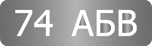
Wrong: cut letters without bridges
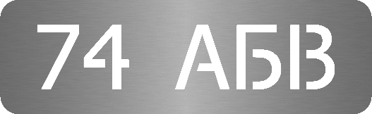
Correct: cut letters with bridges
Corner Rounding
For better cut quality, use a corner radius of at least 0.3 mm. This can vary significantly depending on the material thickness. If you need very small radii for design reasons, note that requirement in the comment field of your order.
Rounding Corners in Slot-and-Tab Assemblies
Inner contour corners also become rounded during laser cutting, which can cause problems for plug-in or slot-and-tab connections. In such cases it makes sense to add relief holes in the corners to ensure fit-up.
|
|
|


Material Availability
To check material availability for the required sheet thickness, see the Materials Catalog page. For project-specific questions, use the Contact page.