Guidelines for press brake bent parts
This page summarizes the design rules and production limits for parts bent on a press brake. It covers dimensional limits, drawing requirements, bend geometry, hole distances, bend radii, flat-pattern compensation, corner relief, and tool-collision risks.
Part Limits
- Maximum bend length: 2980 mm
- Maximum steel sheet thickness: 10 mm
- Maximum stainless steel sheet thickness: 8 mm
- Maximum aluminum sheet thickness: 6 mm
- Maximum weight of a bent part: 100 kg
Depending on the material, only certain sheet sizes are possible. See the Materials Catalog page for the available materials and size ranges.
Technical Drawing Requirement
Technical drawings in PDF format are required for bent parts. The attached vector CAD file is used as the cutting file, while additional information such as tolerances and bending notes must be shown in the PDF drawing because they cannot be interpreted automatically. If there is a discrepancy between the CAD and PDF files, production is based on the CAD file when possible.
Important Notes
- For thin sheet parts, micro-bridges can be added during cutting to prevent parts from tipping and colliding with the laser head.
- Some CAD programs export DXF files with layers or levels that can alter the contour. Such issues may not be recognized automatically.
- Cut edge characteristics and cut quality can vary depending on the production process.
- Depending on the material and process steps, the raw surface may be oily or, in the case of steel, slightly rusty. Untreated surfaces may also retain visible markings.
- Because laser cutting is a thermal process, cut edges and cut angles can vary with material thickness.
- If your part has special surface requirements, describe them in the order comment.
- With one-sided burr removal selected, the underside of the CAD file is chosen automatically.
Tolerances
By default, press brake bent parts in Laser Master are produced according to the tolerances referenced in BDS EN ISO 22768-m.
Maximum Bend Length by Material and Thickness
To ensure manufacturability, the design has to respect the limit imposed by the bending tools and machine setup.
| Sheet thickness t [mm] | 0.5 | 0.6 | 0.8 | 1 | 1.2 | 1.5 | 2 | 2.5 | 3 | 4 | 5 | 6 | 8 | 10 |
|---|---|---|---|---|---|---|---|---|---|---|---|---|---|---|
| S235 | 3000 | 3000 | 3000 | 3000 | 3000 | 3000 | 3000 | 3000 | 3000 | 2600 | 2500 | 1700 | 1300 | 1000 |
| S275 | 3000 | 3000 | 3000 | 3000 | 3000 | 3000 | 3000 | 3000 | 3000 | 2300 | 2200 | 1500 | 1100 | 900 |
| S355 | 3000 | 3000 | 3000 | 3000 | 3000 | 3000 | 3000 | 3000 | 2600 | 1950 | 1900 | 1300 | 950 | 750 |
| EN 1.4301 / AISI 304 | 3000 | 3000 | 3000 | 3000 | 3000 | 3000 | 3000 | 3000 | 2500 | 1900 | 1800 | 1200 | 950 | 750 |
| Aluminum | 3000 | 3000 | 3000 | 3000 | 3000 | 3000 | 3000 | 3000 | 3000 | 3000 | 3000 | 3000 | 3000 | 3000 |
Minimum and Maximum Dimensions at the Bend
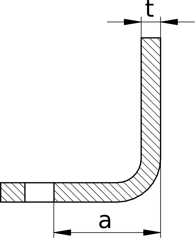
If the bend leg is too short for the required die opening, the bend cannot be produced. The exact values can vary depending on component geometry and bend length.
|
|
|


Minimum dimensions for bending
The table below shows the minimum bend leg dimension a in mm, depending on sheet thickness t and bend angle.
| Sheet thickness t [mm] | 0.5 | 0.6 | 0.8 | 1 | 1.2 | 1.5 | 2 | 2.5 | 3 | 4 | 5 | 6 | 8 | 10 |
|---|---|---|---|---|---|---|---|---|---|---|---|---|---|---|
| a [mm] at 45° | 10.7 | 10.7 | 10.7 | 10.7 | 10.7 | 16.1 | 21.4 | 21.4 | 32.1 | 42.8 | 64.3 | 64.3 | 85.7 | 107.1 |
| a [mm] at 90° | 5.8 | 5.8 | 5.8 | 5.8 | 5.8 | 8.7 | 11.5 | 11.5 | 17.3 | 23.1 | 34.6 | 34.6 | 46.2 | 57.7 |
| a [mm] at 135° | 4.4 | 4.4 | 4.4 | 4.4 | 4.4 | 6.6 | 8.8 | 8.8 | 13.2 | 17.6 | 26.3 | 26.3 | 35.1 | 43.9 |
Maximum dimensions for bending
Maximum dimensions for bending: a = 500 mm.
Minimum Distance to Holes and Cutouts
If holes or notches are too close to the bend line, they can deform during bending. The minimum distance to a hole follows the same rule as the minimum bend-leg length described above.
|
|
|
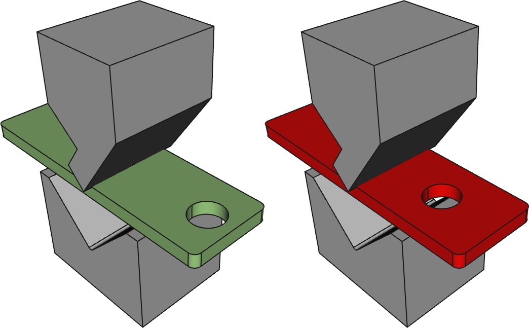
If a hole or contour has to stay close to the bend line for design reasons, additional relief holes can be designed in the bend zone. Laser Master cannot take responsibility for design-related distortion in such cases.
Additional Relief Holes
If the minimum distance to holes cannot be maintained, additional relief holes can reduce distortion of the main holes near the bend area.
- There must still be enough material in the bend area to maintain part stability.
- Sharp-cornered cutouts such as rectangles often become crack initiators because the material is weakened at the corners.
- The preferred shape for additional relief openings in the bend area is a rounded rectangle.

Sharp Corners and External Contours Near the Bend Line
If a part has sharp corners or other outer contours close to the bend edge, the same minimum bend-length rules apply. Once the contour becomes too short, the material no longer sits fully on the lower tool, which can lead to deformation or incomplete bending.

Incorrect

Correct
Minimum Bend Radius
Internal bend radii are determined mainly by the choice of lower die, while the punch has only limited influence. Actual radii can also vary with material batch, tool condition, and part geometry.
| Sheet thickness t [mm] | 0.5 | 0.6 | 0.8 | 1 | 1.2 | 1.5 | 2 | 2.5 | 3 | 4 | 5 | 6 | 8 | 10 |
|---|---|---|---|---|---|---|---|---|---|---|---|---|---|---|
| Correction factor (ISO/DIN) | 0.85 | 0.81 | 0.75 | 0.70 | 0.75 | 0.70 | 0.70 | 0.74 | 0.70 | 0.70 | 0.74 | 0.70 | 0.70 | 0.70 |
| Correction factor (ASTM) | 0.42 | 0.40 | 0.37 | 0.35 | 0.37 | 0.35 | 0.35 | 0.37 | 0.35 | 0.35 | 0.37 | 0.35 | 0.35 | 0.35 |
| Minimum bend radius r [mm] | 1.25 | 1.25 | 1.25 | 1.25 | 1.25 | 1.875 | 2.5 | 3.75 | 3.75 | 5 | 7.5 | 7.5 | 10.0 | 12.5 |
| Possible bend radii r [mm] | 1.875, 2.5, 3.75, 5, 7.5, 10, 12.5 | 1.875, 2.5, 3.75, 5, 7.5, 10, 12.5 | 1.875, 2.5, 3.75, 5, 7.5, 10, 12.5 | 1.875, 2.5, 3.75, 5, 7.5, 10, 12.5 | 1.875, 2.5, 3.75, 5, 7.5, 10, 12.5 | 2.5, 3.75, 5, 7.5, 10, 12.5 | 3.75, 5, 7.5, 10, 12.5 | 5, 7.5, 10, 12.5 | 5, 7.5, 10, 12.5 | 7.5, 10, 12.5 | 10, 12.5 | 10, 12.5 | 12.5 |
Flat-Pattern Size Compensation
The length of the unfolded laser-cut blank is the sum of the bent-part flange dimensions minus the compensation value v.
Formulas
L = a + b - va* = a - v / 2b* = b - v / 2
Here, L is the flat pattern length and the bend line sits between the compensated flange dimensions a* and b*.
| Sheet thickness t [mm] | 0.5 | 0.6 | 0.8 | 1 | 1.2 | 1.5 | 2 | 2.5 | 3 | 4 | 5 | 6 | 8 | 10 |
|---|---|---|---|---|---|---|---|---|---|---|---|---|---|---|
| K-factor correction (ISO/DIN) | 0.85 | 0.81 | 0.75 | 0.70 | 0.75 | 0.70 | 0.70 | 0.74 | 0.70 | 0.70 | 0.74 | 0.70 | 0.70 | 0.70 |
| K-factor correction (ASTM) | 0.42 | 0.40 | 0.37 | 0.35 | 0.37 | 0.35 | 0.35 | 0.37 | 0.35 | 0.35 | 0.37 | 0.35 | 0.35 | 0.35 |
| Bend radius r [mm] | 1.25 | 1.25 | 1.25 | 1.25 | 1.25 | 1.875 | 2.5 | 3.75 | 3.75 | 5 | 7.5 | 7.5 | 10.0 | 12.5 |
| v [mm] at 45° | 0.05 | 0.18 | 0.45 | 0.73 | 0.68 | 1.10 | 1.46 | 1.49 | 2.20 | 2.93 | 2.98 | 4.39 | 5.86 | 7.32 |
| v [mm] at 90° | 1.20 | 1.36 | 1.67 | 1.99 | 2.50 | 2.98 | 3.98 | 5.16 | 5.96 | 7.95 | 10.32 | 11.93 | 15.90 | 19.88 |
| v [mm] at 135° | 0.30 | 0.36 | 0.48 | 0.61 | 0.72 | 0.91 | 1.22 | 1.51 | 1.82 | 2.43 | 3.02 | 3.65 | 4.86 | 6.08 |
For calculation help, use the DIN 6935 bending calculator page.
Corner Relief
If no small clearance is left at the bend corner, the material can tear along the cut. Adding relief clearance prevents this and allows the part to be bent correctly.

Incorrect

Correct
Tool Collision in U-Profiles
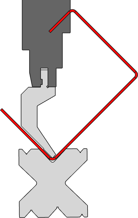
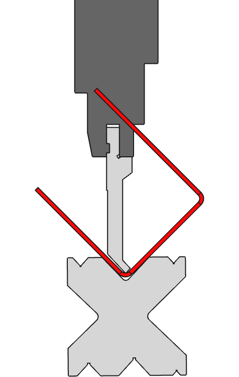
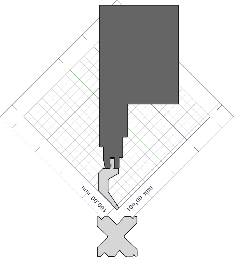
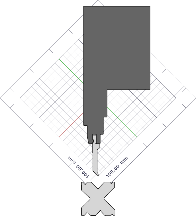
If the bend dimension is too long or the designed U-profile is too narrow, a collision with the upper tool or the clamping beam can occur. The following graphics illustrate both the collision risk and the achievable tool configurations for U-shaped profiles.
|
|
|
|
U-shaped profiles collision risk |
|
|
|
|
|
Achievable tool configurations for U-shaped profiles |
|
Related Pages
Check the Materials Catalog for sheet availability, the Design Guidelines overview for related process rules, and the Contact page for project-specific questions.